
6
TM 5-2410-241-23-3
FIELD MAINTENANCE INSTRUCTIONS
-
PILOT VALVE SERVICE (WITH RIPPER)
02
56
Removal, Cleaning and Inspection, Installation
Effectivity Notice (With Ripper)
INITIAL SETUP
Tools and Special Tools
References
0
0
Tool Kit, General Mechanic's
0
(WP 0302, Item 65)
0
Equipment Condition
0
Materials/Parts
0
Bulldozer pilot valve removed (WP 0259)
0
Cap Set, Protective (WP 0303, Item 4)
0
Drawing Required
0
Rag, Wiping (WP 0303, Item 24)
0
TM 5-2410-241-24P, Figure 74, 115
0
Tag, Marker (WP 0303, Item 34)
0
Estimated Time to Complete
Gasket
0
0
O-ring (12)
0
7.0 Hr
0
REMOVAL
000256
N OT E
Tag hoses to aid installation.
Cap and plug all hoses to prevent contamination and leaks.
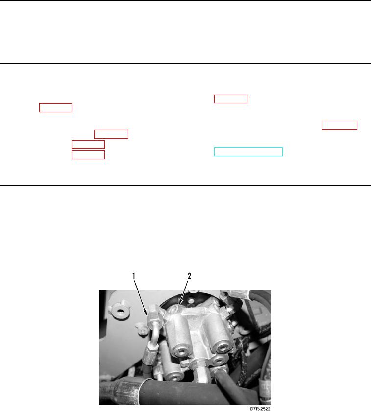
1. Disconnect six hoses (Figure 1, Item 1) from pilot valve (Figure 1, Item 2).
Figure 1. Hoses and Pilot Valve.
0256