
TM 5-2410-241-23-3
0256
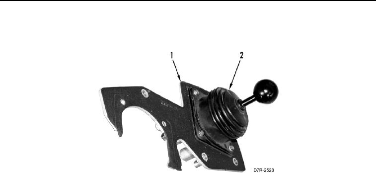
REMOVAL CONTINUED
2. Remove pilot valve and hand control assembly (Figure 2, Item 2) and plate (Figure 2, Item 1) from machine.
Figure 2. Pilot Valve and Hand Control Assembly.
0256
3. Unscrew and remove knob (Figure 3, Item 1) from assembly.
4. Remove four bolts (Figure 3, Item 10), washers (Figure 3, Item 9) and lever assembly (Figure 3, Item 2) from
base plate (Figure 3, Item 4).
N OT E
Note orientation of retainer plate.
5. Remove retainer plate (Figure 3, Item 7) from lever assembly (Figure 3, Item 2).
6. Remove boot (Figure 3, Item 3) from lever assembly (Figure 3, Item 2).