
TM 5-2410-241-23-3
0257
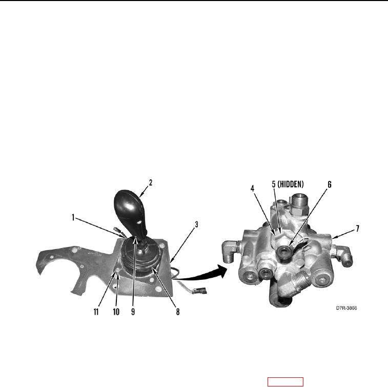
REMOVAL CONTINUED
3. Remove winch pilot valve (Figure 2, Item 1) and plate (Figure 2, Item 3) from machine and place on suitable
work bench.
N OT E
Note position and orientation of fittings to aid installation.
4. Remove six O-rings (Figure 2, Item 6) from fittings (Figure 2, Item 4). Discard O-rings.
5. Remove six fittings (Figure 2, Item 4) and O-rings (Figure 2, Item 5) from valve body (Figure 2, Item 7). Discard
O-rings.
6. Remove four bolts (Figure 2, Item 11), washers (Figure 2, Item 10) and pilot valve (Figure 2, Item 1) from plate
(Figure 2, Item 3).
7. Loosen set screw (Figure 2, Item 9) and remove handle (Figure 2, Item 2) and boot (Figure 2, Item 8) from pilot
valve (Figure 2, Item 1).
Figure 2. Winch Pilot Valve and Plate Assembly.
0257
END OF TASK
CLEANING AND INSPECTION
000257
Clean and inspect all parts IAW Mechanical General Maintenance Instructions (WP 0295).
END OF TASK