
TM 5-2410-241-23-3
0256
INSTALLATION
000256
N OT E
Install fittings and O-rings as noted during removal.
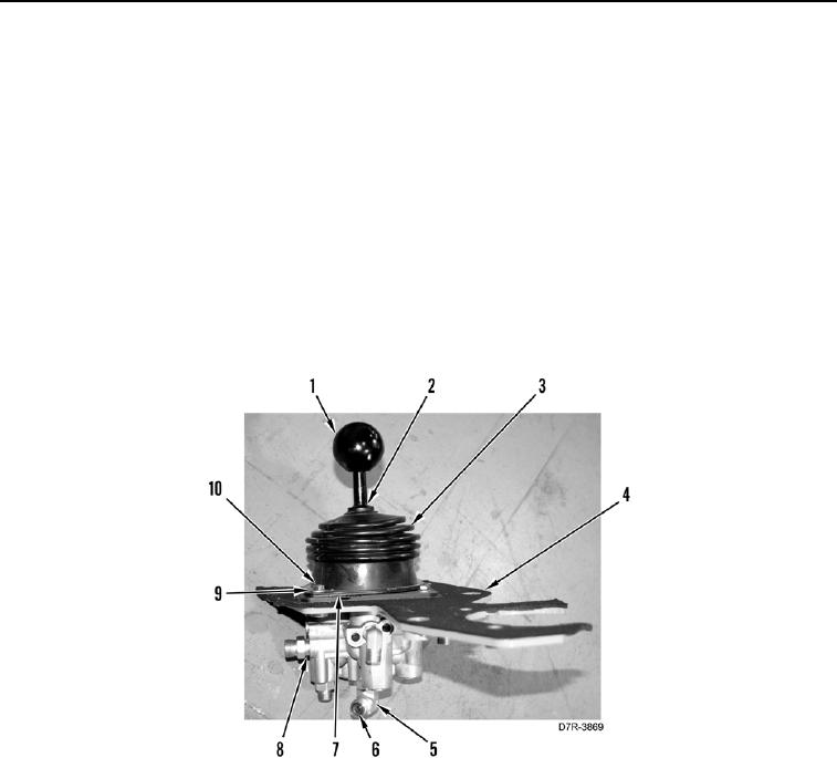
1. Install 12 new O-rings (Figure 4, Item 6) and 6 fittings (Figure 4, Item 5) on valve body (Figure 4, Item 8).
N OT E
Install retainer plate as noted during removal.
2. Install boot (Figure 4, Item 3), and retainer plate (Figure 4, Item 7) on lever assembly (Figure 4, Item 2).
3. Install lever assembly (Figure 4, Item 2), four washers (Figure 4, Item 9) and bolts (Figure 4, Item 10) on base
plate (Figure 4, Item 4).
4. Screw knob (Figure 4, Item 1) on assembly.
Figure 4. Knob, Base Plate and Fittings.
0256