
TM 5-2410-241-23-3
0257
INSTALLATION
000257
N OT E
Install fittings as noted during disassembly.
1. Install boot (Figure 2, Item 8), handle (Figure 2, Item 2) and tighten set screw (Figure 2, Item 9) on pilot valve
(Figure 2, Item 1).
2. Install pilot valve (Figure 2, Item 1), four washers (Figure 2, Item 10) and bolts (Figure 2, Item 11) on plate
(Figure 2, Item 3).
3. Install six new O-rings (Figure 2, Item 5) and fittings (Figure 2, Item 1) on valve body (Figure 2, Item 7).
4. Install six O-rings (Figure 2, Item 6) on fittings (Figure 2, Item 4).
5. Position winch pilot valve assembly (Figure 2, Item 1) and plate (Figure 2, Item 3) on machine.
N OT E
Install hoses as tagged during removal.
Connect wiring harness connectors as tagged during removal.
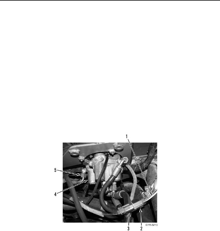
6. Connect two pilot valve wire harness connectors (Figure 3, Items 2 and 3) to machine harnesses (Figure 3,
Item 1).
7. Connect six hoses (Figure 3, Item 5) to pilot valve (Figure 3, Item 4).
Figure 3. Hoses and Pilot Valve.
0257
END OF TASK