
4
TM 5-2410-241-23-3
FIELD MAINTENANCE INSTRUCTIONS
-
PILOT VALVE SERVICE (WITH WINCH)
0257
Removal, Cleaning and Inspection, Installation
Effectivity Notice (With Winch)
INITIAL SETUP
Tools and Special Tools
Equipment Condition
0
0
Tool Kit, General Mechanic's
Machine parked (TM 5-2410-241-10)
0
(WP 0302, Item 65)
0
Seat suspension removed (WP 0248)
0
Right access panels removed (WP 0208)
0
Materials/Parts
0
Bulldozer pilot valve removed (WP 0259)
0
Rag, Wiping (WP 0303, Item 24)
0
Drawing Required
Tag, Marker (WP 0303, Item 34)
0
0
O-ring (16)
0
TM 5-2410-241-24P, Figure 116
0
References
Estimated Time to Complete
0
0
7.5 Hr
0
0
REMOVAL
000257
N OT E
Tag hoses to aid installation.
Tag electrical connectors to aid installation.
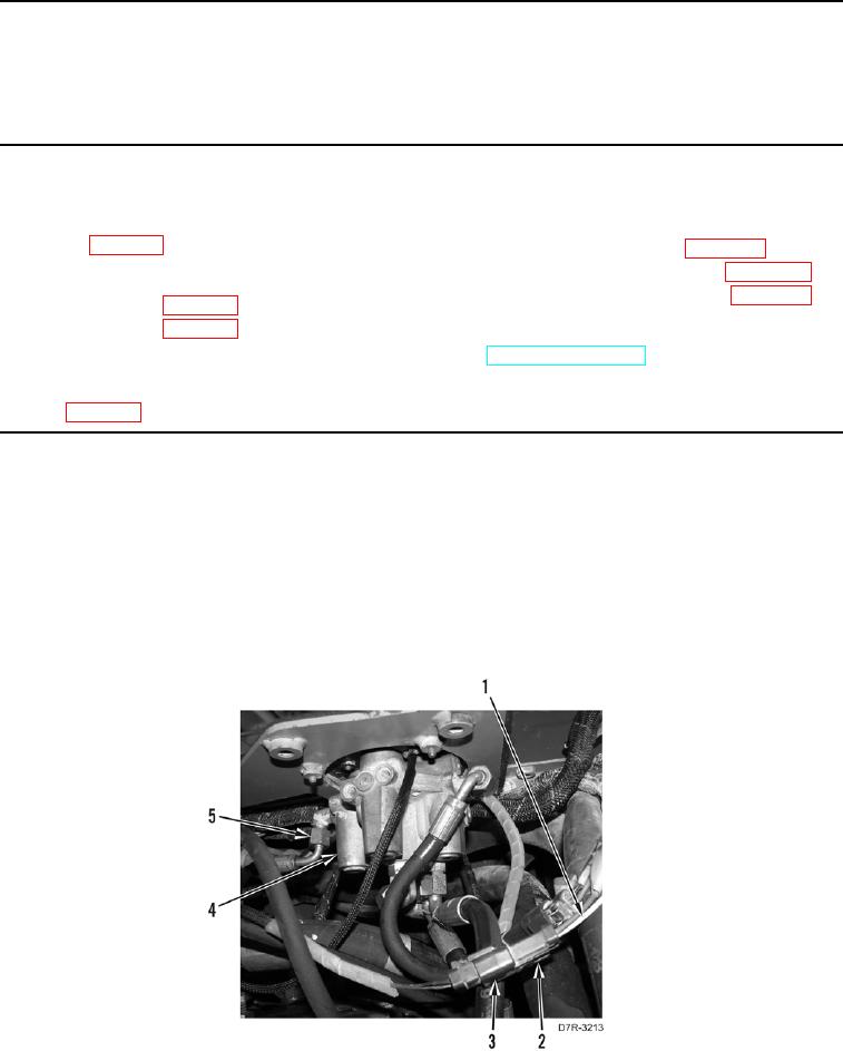
1. Disconnect six hoses (Figure 1, Item 5) from pilot valve (Figure 1, Item 4).
2. Disconnect two pilot valve wire harness connectors (Figure 1, Items 2 and 3) from machine harnesses
(Figure 1, Item 1).
Figure 1. Winch Pilot Valve Hoses and Connectors.
0257