
TM 5-2410-241-23-3
0212
INSTALLATION CONTINUED
N OT E
Install hoses as noted during removal.
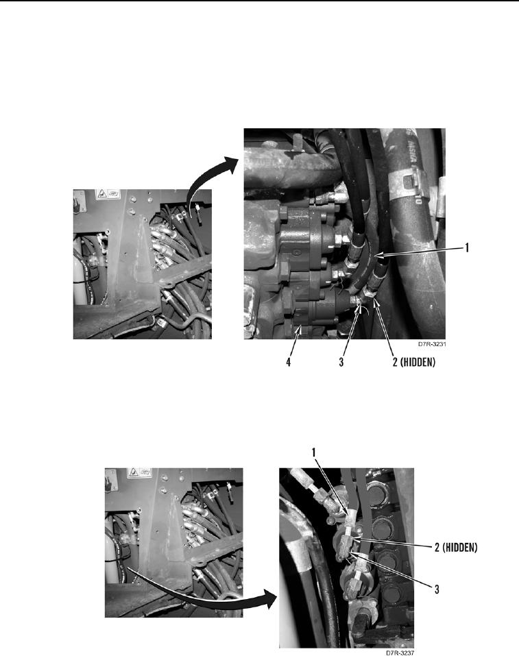
9. Install two new O-rings (Figure 27, Item 2) and two hoses (Figure 27, Item 1), on fittings (Figure 27, Item 3) at
valve bank (Figure 27, Item 4)
Figure 27. Hose Connections at Rear of Valve Bank.
0212
10. Install three new O-rings (Figure 28, Item 2) on fittings (Figure 28, Item 3) and connect hoses (Figure 28,
Item 1).
Figure 28. Hose Connections at Front of Valve Bank.
0212