
TM 5-2410-241-23-3
0214
ASSEMBLY
000214
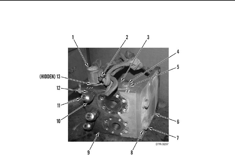
1. Install mounting bracket (Figure 4, Item 6), two washers (Figure 4, Item 8), bolts (Figure 4, Item 7) on manifold
(Figure 4, Item 9).
Figure 4. Winch Manifold.
0214
N OT E
Install fittings as noted during disassembly.
2. Install six new O-rings (Figure 4, Item 12) and fittings (Figure 4, Item 10) on manifold (Figure 4, Item 9).
3. Install six new O-rings (Figure 4, Item 11) on fittings (Figure 4, Item 10).
4. Install bracket (Figure 4, Item 3), washer (Figure 4, Item 5), and bolt (Figure 4, Item 4) on manifold.
5. Install new O-ring (Figure 4, Item 13) and solenoid (Figure 4, Item 1) on manifold (Figure 4, Item 9).
6. Install new tiedown strap (Figure 4, Item 2).