
TM 5-2410-241-23-3
0229
REAR HEADLINER REMOVAL CONTINUED
Note harness routing to aid installation.
Tag and mark all electrical connections to aid installation.
Note number and location of tiedown straps to aid installation.
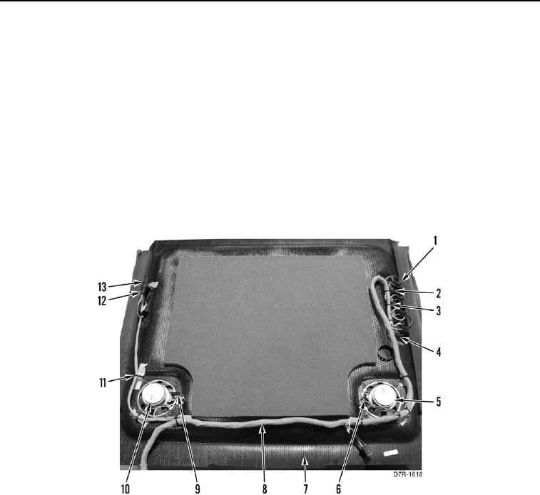
7. Disconnect 21 electrical connectors (Figure 8, Item 1) from four wiper control switches (Figure 8, Item 2).
8. Remove tiedown straps (Figure 8, Item 3) from wiper control plate assembly (Figure 8, Item 4). Discard
tiedown straps.
9. Disconnect two electrical connectors (Figure 8, Item 6) from speaker (Figure 8, Item 5).
10. Disconnect two electrical connectors (Figure 8, Item 9) from speaker (Figure 8, Item 10).
11. Disconnect electrical connectors (Figure 8, Item 13) from light electrical connectors (Figure 8, Item 12).
12. Remove tiedown straps (Figure 8, Item 11) from harness (Figure 8, Item 8) and headliner (Figure 8, Item 7).
13. Remove harness (Figure 8, Item 8) from headliner (Figure 8, Item 7).
Figure 8. Headliner Harness.
0229
END OF TASK