
TM 5-2410-241-23-3
0237
REMOVAL CONTINUED
N OT E
Note location and quantity of tiedown straps to aid installation.
Tag wiring harness to aid installation.
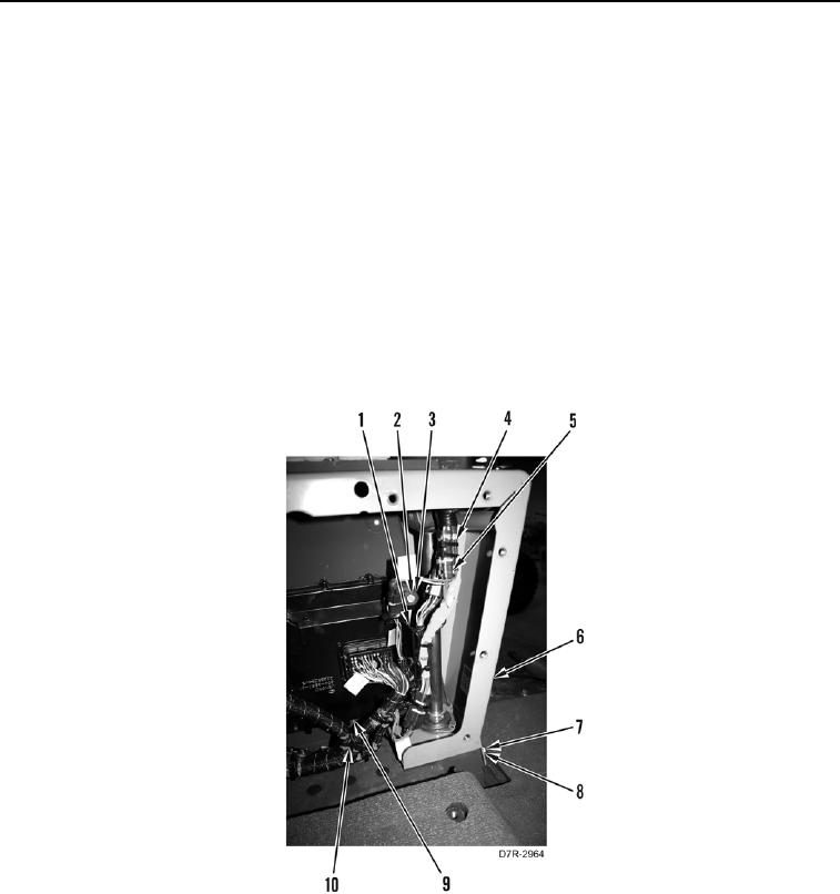
4. Remove tiedown straps (Figure 2, Item 4) from wiring harness (Figure 2, Item 10). Discard tiedown straps.
5. Disconnect four wiring harness connectors (Figure 2, Item 5) from wiring harness (Figure 2, Item 10).
N OT E
Secure grommets to ECM after removing bolts.
6. Remove two bolts (Figure 2, Item 2), washers (Figure 2, Item 3), and bracket (Figure 2, Item 1) from ECM
(Figure 2, Item 9).
7. Remove three bolts (Figure 2, Item 8), washers (Figure 2, Item 7), and steering control housing (Figure 2,
Item 6) from machine.
Figure 2. Steering Control Housing.
0237
END OF TASK