
TM 5-2410-241-23-3
0237
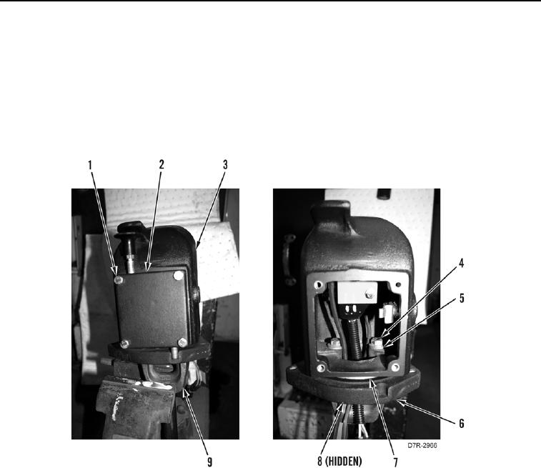
DISASSEMBLY CONTINUED
8. Remove four bolts (Figure 5, Item 1) and parking brake control (Figure 5, Item 2) from main control housing
(Figure 5, Item 3).
9. Remove two bolts (Figure 5, Item 4), washers (Figure 5, Item 5), and main control housing (Figure 5, Item 3)
from shaft (Figure 5, Item 9).
10. Remove bearing housing (Figure 5, Item 6) from bearing (Figure 5, Item 7) and main control housing (Figure 5,
Item 3).
11. Remove O-ring (Figure 5, Item 8) from bearing housing (Figure 5, Item 6). Discard O-ring.
Figure 5. Main Control Housing.
0237