
TM 5-2410-241-23-3
0237
DISASSEMBLY CONTINUED
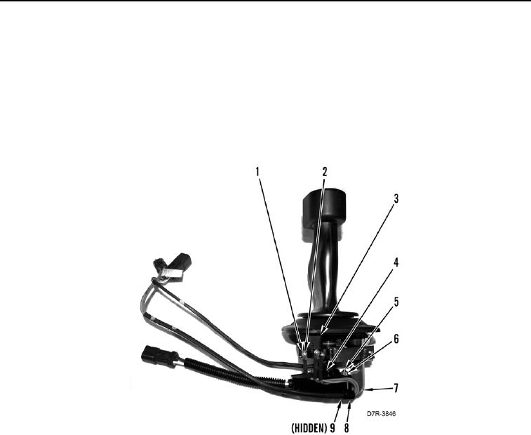
24. Remove bolt (Figure 12, Item 9), nut (Figure 12, Item 5), washer (Figure 12, Item 6), clip (Figure 12, Item 8),
and wires (Figure 12, Item 4) from bracket (Figure 12, Item 7).
N OT E
Tag wires to aid installation.
25. Remove three bolts (Figure 12, Item 1), lockwashers (Figure 12, Item 2), and wires (Figure 12, Item 4) from
backup alarm switch (Figure 12, Item 3). Discard lockwashers.
Figure 12. Backup Alarm Switch Connections.
0237