
TM 5-2410-241-23-3
0237
DISASSEMBLY CONTINUED
N OT E
Note orientation of tab on lock assembly to aid installation.
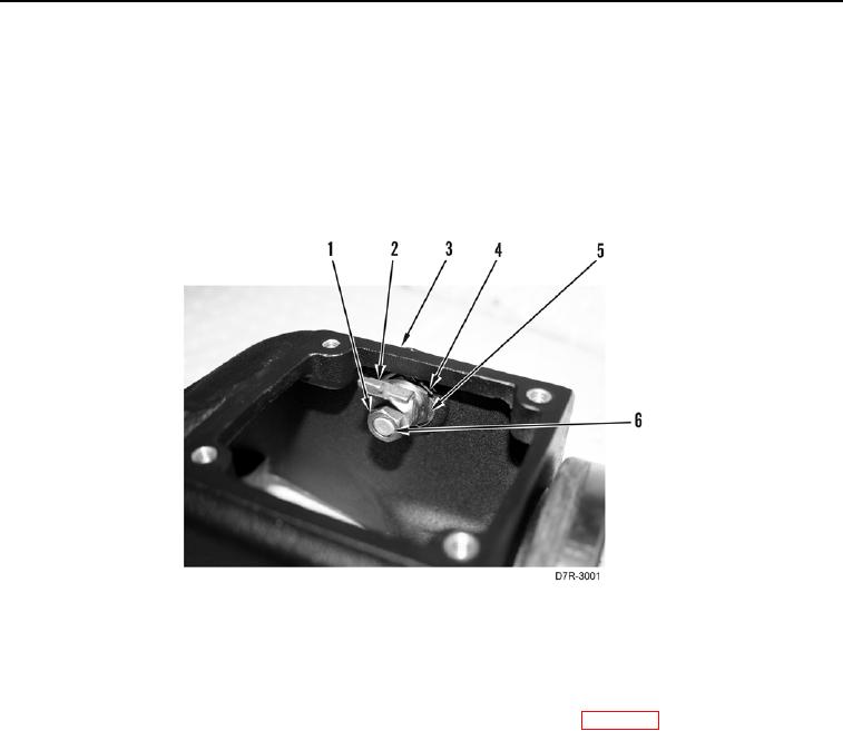
33. Remove nut (Figure 19, Item 1) and tab (Figure 19, Item 2) from lock assembly (Figure 19, Item 6).
34. Open lock tab (Figure 19, Item 4) and remove nut (Figure 19, Item 5) and lock assembly (Figure 19, Item 6).
from main control housing (Figure 19, Item 3).
Figure 19. Lock Assembly.
0237
END OF TASK
CLEANING AND INSPECTION
000237
Clean and inspect all parts IAW Mechanical General Maintenance Instructions (WP 0295).
END OF TASK