• Home
  • Download PDF
  • Order CD-ROM
  • Order in Print
Figure 10. Shafts.
Figure 12. Backup Alarm Switch Connections.

Field Maintenance Manual 3 D7R Dozer Type I With Winch and Type II With Ripper
Page Navigation
  451    452    453    454    455  456  457    458    459    460    461  
img
.
TM 5-2410-241-23-3
0237
DISASSEMBLY CONTINUED
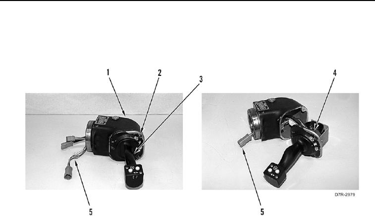
22. Remove three bolts (Figure 11, Item 2) and pull handle assembly (Figure 11, Item 3) and wiring harnesses
(Figure 11, Item 5) from main control housing (Figure 11, Item 1).
23. Remove gasket (Figure 11, Item 4) from handle assembly (Figure 11, Item 3). Discard gasket.
Figure 11. Handle Assembly.
0237
0237-10


Privacy Statement
Press Release
Contact

© Copyright Integrated Publishing, Inc.. All Rights Reserved.