
TM 5-2410-241-23-3
0237
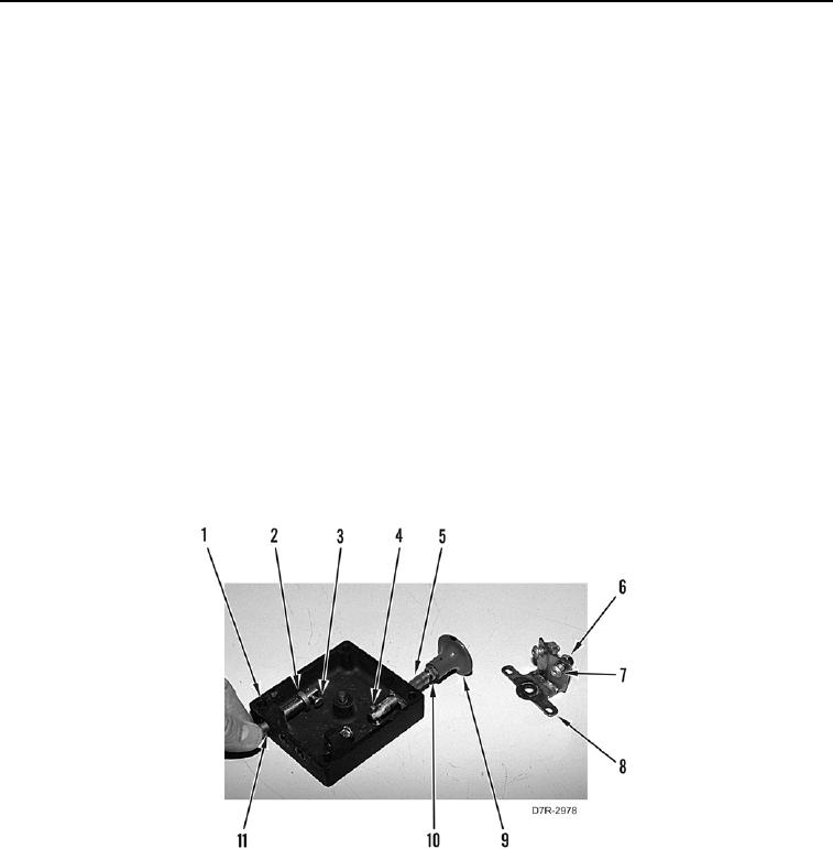
DISASSEMBLY CONTINUED
N OT E
Note orientation of shaft and pin.
17. Rotate shaft (Figure 10, Item 2) and remove pin (Figure 10, Item 3) from shaft. Remove shaft from parking
brake control cover (Figure 10, Item 1).
18. Rotate shaft (Figure 10, Item 5) and remove pin (Figure 10, Item 4) from shaft. Remove shaft from parking
brake control cover (Figure 10, Item 1).
N OT E
Note position of bolts on plate to aid installation.
19. Remove two nuts (Figure 10, Item 6) and bolts (Figure 10, Item 7) from plate (Figure 10, Item 8).
20. Remove two seals (Figure 10, Item 11) from parking brake control cover (Figure 10, Item 1). Discard seals.
N OT E
Note position of knob and jam nut on shaft to aid installation.
21. Loosen jam nut (Figure 10, Item 10) and remove knob (Figure 10, Item 9) and jam nut from shaft (Figure 10,
Item 5).
Figure 10. Shafts.
0237