• Home
  • Download PDF
  • Order CD-ROM
  • Order in Print
Figure 12. Backup Alarm Switch Connections.
Figure 15. Forward/Neutral/Reverse Sensor.

Field Maintenance Manual 3 D7R Dozer Type I With Winch and Type II With Ripper
Page Navigation
  453    454    455    456    457  458  459    460    461    462    463  
img
.
TM 5-2410-241-23-3
0237
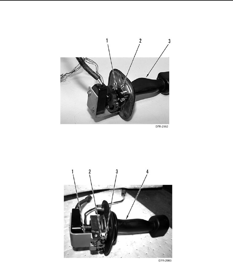
DISASSEMBLY CONTINUED
26. Remove two bolts (Figure 13, Item 1) and backup alarm switch (Figure 13, Item 2) from handle assembly
(Figure 13, Item 3).
Figure 13. Backup Alarm Switch.
0237
27. Remove two bolts (Figure 14, Item 2), washers (Figure 14, Item 3), and bracket (Figure 14, Item 1) from handle
assembly (Figure 14, Item 4).
Figure 14. Sensor Bracket.
0237
0237-12


Privacy Statement
Press Release
Contact

© Copyright Integrated Publishing, Inc.. All Rights Reserved.