• Home
  • Download PDF
  • Order CD-ROM
  • Order in Print
Figure 19. Lock Assembly.
Figure 21. Main Control Housing Bearing.

Field Maintenance Manual 3 D7R Dozer Type I With Winch and Type II With Ripper
Page Navigation
  457    458    459    460    461  462  463    464    465    466    467  
img
.
TM 5-2410-241-23-3
0237
ASSEMBLY
000237
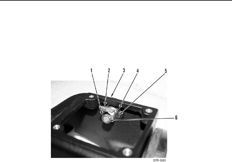
1. Install lock assembly (Figure 20, Item 6), lock tab (Figure 20, Item 4), and nut (Figure 20, Item 5) on main
control housing (Figure 20, Item 3). Secure lock tab.
N OT E
Install tab on lock assembly as noted in removal.
2. Install tab (Figure 20, Item 2) and nut (Figure 20, Item 1) on lock assembly (Figure 20, Item 6).
Figure 20. Lock Assembly.
0237
0237-16


Privacy Statement
Press Release
Contact

© Copyright Integrated Publishing, Inc.. All Rights Reserved.