
TM 5-2410-241-23-3
0237
ASSEMBLY CONTINUED
N OT E
Install wires as tagged during removal.
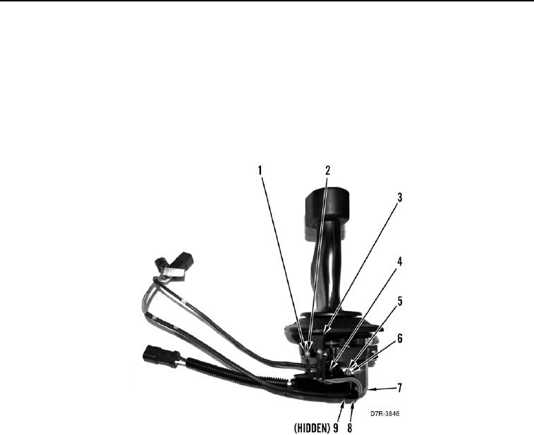
10. Install three wires (Figure 27, Item 4), new lockwashers (Figure 27, Item 2), and bolts (Figure 27, Item 1) on
backup alarm switch (Figure 27, Item 3).
11. Install wires (Figure 27, Item 3), clip (Figure 27, Item 8), bolt (Figure 27, Item 9), washer (Figure 27, Item 6),
and nut (Figure 27, Item 5) on bracket (Figure 27, Item 7).
Figure 27. Backup Alarm Switch Connections.
0237