
TM 5-2410-241-23-3
0237
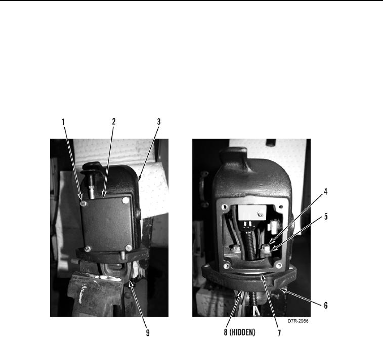
ASSEMBLY CONTINUED
24. Install new O-ring (Figure 34, Item 8) on bearing housing (Figure 34, Item 6).
25. Install bearing housing (Figure 34, Item 6) on bearing (Figure 34, Item 7) on main control housing (Figure 34,
Item 3).
26. Install main control housing (Figure 34, Item 3), two washers (Figure 34, Item 5), and bolts (Figure 34, Item 4)
on shaft (Figure 34, Item 9).
27. Install parking brake control (Figure 34, Item 2) and four bolts (Figure 34, Item 1) on main control housing
(Figure 34, Item 3).
Figure 34. Main Control Housing.
0237