
TM 5-2410-241-23-3
0237
INSTALLATION CONTINUED
N OT E
Install lever on shaft as noted in removal.
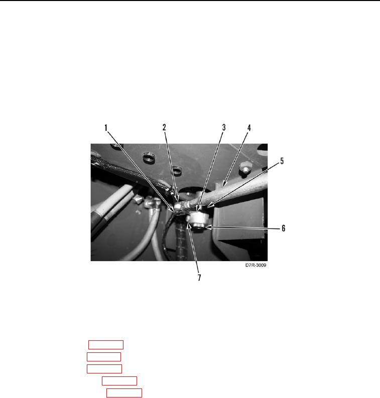
5. Install spacer (Figure 38, Item 5) and lever (Figure 38, Item 3) on shaft (Figure 38, Item 6) and tighten bolt
(Figure 38, Item 7).
6. Connect steering control rod (Figure 38, Item 4) to lever (Figure 38, Item 3) and install pin (Figure 38, Item 2).
7. Install retainer (Figure 38, Item 1) on steering control rod (Figure 38, Item 4).
Figure 38. Steering Control Rod.
0237
END OF TASK
FOLLOW-ON TASKS
000237
1. Install front floor plate (WP 0230).
2. Install rear floor plate (WP 0231).
3. Install left cover plate (WP 0207).
4. Install left upper left panel (WP 0207).
5. Install left armrest removed (WP 0207).
6. Verify correct operation of machine (TM 5-2410-241-10).
END OF TASK
END OF WORK PACKAGE