
TM 5-2410-241-23-3
0238
INSTALLATION
000238
N OT E
Install levers as noted during removal.
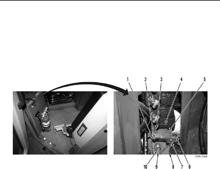
1. Install lever (Figure 4, Item 5) on shaft (Figure 4, Item 6) and tighten bolt (Figure 4, Item 7).
2. Repeat step 1 for other lever.
3. Install bracket (Figure 4, Item 8), three washers (Figure 4, Item 9) and bolts (Figure 4, Item 10) on machine.
4. Install link (Figure 4, Item 3), two washers (Figure 4, Item 2), and new cotter pins (Figure 4, Item 1) on control
valve (Figure 4, Item 4) and lever (Figure 4, Item 5).
Figure 4. Bracket. (Hydraulic lines removed for clarity).
0238