
6
TM 5-2410-241-23-3
FIELD MAINTENANCE
-
STEERING CONTROL ROD REPLACEMENT
023
8
Removal, Adjustment, Installation
INITIAL SETUP
Equipment Condition - Continued
Tools and Special Tools
0
0
Front floor plate removed (WP 0230)
0
Tool Kit, General Mechanic's
(WP 0302, Item 65)
0
Right platform access panel removed (WP
0
Materials/Parts
0
Drawing Required
0
Cotter pin (2)
0
TM 5-2410-241-24P, Figure 123
0
Equipment Condition
0
Estimated Time to Complete
0
Machine parked (TM 5-2410-241-10)
0
5.5 Hr
0
REMOVAL
000238
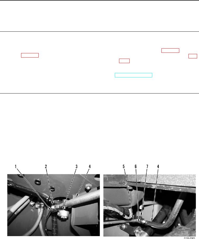
1. Remove retainer pin (Figure 1, Item 1) from yoke (Figure 1, Item 2) and steering and transmission control lever
(Figure 1, Item 3).
2. Remove steering control rod (Figure 1, Item 4) from steering and transmission control lever (Figure 1, Item 3).
N OT E
Note steering control rod orientation to aid installation.
3. Remove retainer pin (Figure 1, Item 7) from yoke (Figure 1, Item 6) and control valve lever (Figure 1, Item 5).
4. Remove steering control rod (Figure 1, Item 4) from control valve lever (Figure 1, Item 5) and machine.
Figure 1. Steering Control Rod.
0238