
TM 5-2410-241-23-3
0237
ASSEMBLY CONTINUED
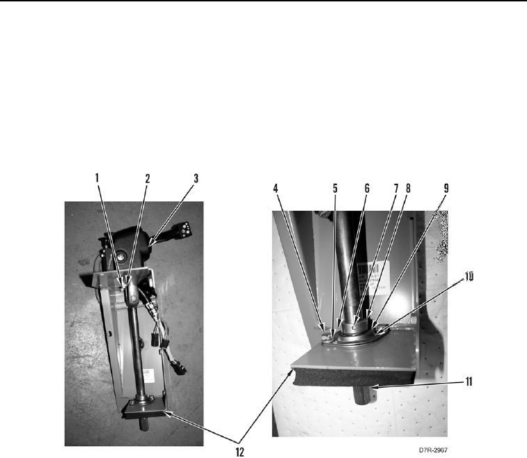
30. Install steering control shaft (Figure 36, Item 11) on steering control housing (Figure 36, Item 12).
31. Install bearing (Figure 36, Item 10), two retainers (Figure 36, Item 9), washers (Figure 36, Item 5), and bolts
(Figure 36, Item 4) on steering control housing (Figure 36, Item 12).
32. Place a punch or drift in hole (Figure 36, Item 7) of collar (Figure 36, Item 8) and strike with hammer in
clockwise direction.
33. Tighten setscrew (Figure 36, Item 6) in collar (Figure 36, Item 8).
34. Install three washers (Figure 36, Item 2) and bolts (Figure 36, Item 1) on main control housing (Figure 36,
Item 3).
Figure 36. Control Console.
0237
END OF TASK