
TM 5-2410-241-23-3
0237
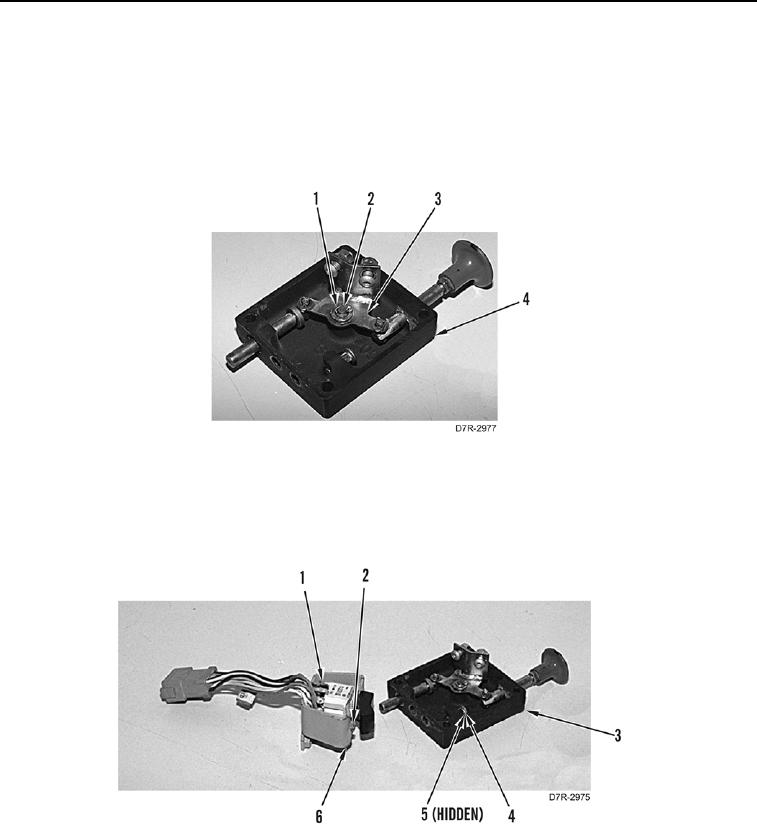
ASSEMBLY CONTINUED
N OT E
Orientate shafts on plate as noted in removal.
19. Install plate (Figure 30, Item 3), three washers (Figure 30, Item 2), and new cotter pins (Figure 30, Item 1) on
parking brake control cover (Figure 30, Item 4).
Figure 30. Plate.
0237
20. Install parking brake switch (Figure 31, Item 1) and two bolts (Figure 31, Item 2) on bracket (Figure 31, Item 6).
21. Install bolt (Figure 31, Item 4) and nut (Figure 31, Item 5) on parking brake control cover (Figure 31, Item 3).
Figure 31. Parking Brake Switch Bracket.
0237