
TM 5-2410-241-23-3
0237
ASSEMBLY CONTINUED
N OT E
Position jam nut and knob on shaft as noted in removal.
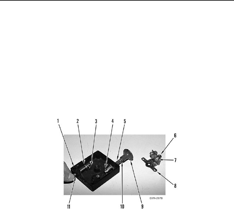
14. Install jam nut (Figure 29, Item 10) and knob (Figure 29, Item 9) on shaft (Figure 29, Item 5). Tighten jam nut.
15. Install two new seals (Figure 29, Item 11) on parking brake control cover (Figure 29, Item 1).
N OT E
Position bolts on plate as noted in removal.
16. Install two bolts (Figure 29, Item 7) and nuts (Figure 29, Item 6) on plate (Figure 29, Item 8).
17. Install shaft (Figure 29, Item 5) in parking brake control cover (Figure 29, Item 1), rotate shaft, and install pin
(Figure 29, Item 4) on shaft.
18. Install shaft (Figure 29, Item 2) in parking brake control cover (Figure 29, Item 1), rotate shaft, and install pin
(Figure 29, Item 3) on shaft.
Figure 29. Shafts.
0237