
TM 5-2410-241-23-3
0238
INSTALLATION CONTINUED
N OT E
Install steering control rod as noted during removal.
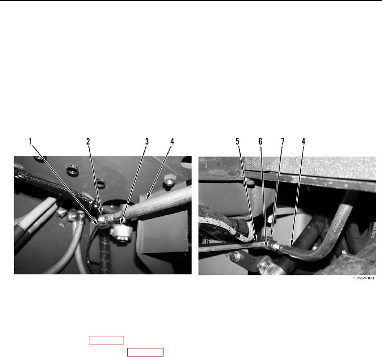
5. Position steering control rod (Figure 5, Item 4) on control valve lever (Figure 5, Item 5).
6. Install yoke (Figure 5, Item 6) and retainer pin (Figure 5, Item 7) on control valve lever (Figure 5, Item 5).
7. Position steering control rod (Figure 5, Item 4) on steering and transmission control lever (Figure 5, Item 3).
8. Install yoke (Figure 5, Item 2) and retainer pin (Figure 5, Item 1) on steering and transmission control lever
(Figure 5, Item 3).
Figure 5. Steering Control Rod.
0238
END OF TASK
FOLLOW-ON TASKS
000238
1. Install front floor plate (WP 0230).
2. Install right platform access panel (WP 0208).
3. Verify correct operation of machine (TM 5-2410-241-10).
END OF TASK
END OF WORK PACKAGE