
TM 5-2410-241-23-3
0243
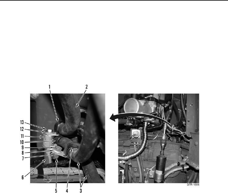
REMOVAL CONTINUED
13. Remove nut (Figure 4, Item 5), washer (Figure 4, Item 7), bolt (Figure 4, Item 9), washer (Figure 4, Item 8), and
retaining strap (Figure 4, Item 4) from two hoses (Figure 4, Item 3).
14. Remove bolt (Figure 4, Item 13), washer (Figure 4, Item 12), retaining strap (Figure 4, Item 1), and hose
(Figure 4, Item 2) from support bracket (Figure 4, Item 6). Position hose aside.
15. Remove spacer (Figure 4, Item 11) and retaining strap (Figure 4, Item 10) from two hoses (Figure 4, Item 3).
N OT E
Tag hoses to aid installation.
16. Remove two hoses (Figure 4, Item 3) from machine.
Figure 4. Rear Engine Connections.
0243