
TM 5-2410-241-23-3
0245
REMOVAL CONTINUED
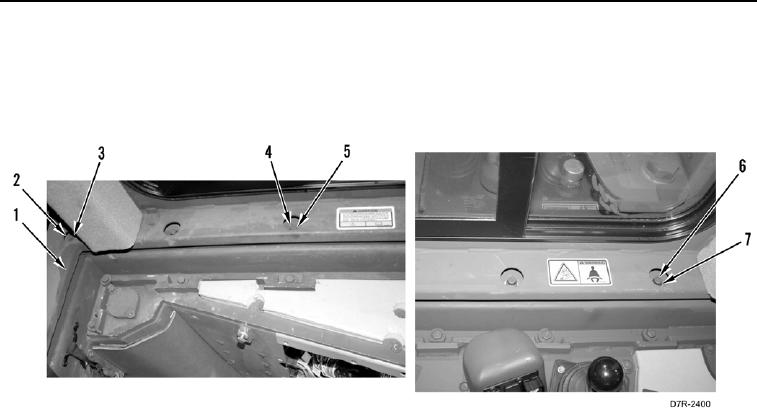
14. Remove three bolts (Figure 5, Item 4) and washers (Figure 5, Item 5) from left side of cab (Figure 5, Item 1).
15. Remove three bolts (Figure 5, Item 6) and washers (Figure 5, Item 7) from right side of cab (Figure 5, Item 1).
16. Remove six bolts (Figure 5, Item 2) and washers (Figure 5, Item 3) from across back of cab (Figure 5, Item 1).
Figure 5. Cab Bolts.
0245