
TM 5-2410-241-23-3
0245
REMOVAL CONTINUED
20. Remove four bolts (Figure 7, Item 3), washers (Figure 7, Item 2), and panel (Figure 7, Item 1) from instrument
panel (Figure 7, Item 4).
Figure 7. Surround.
0245
N OT E
Tag all electrical harness connectors to aid installation.
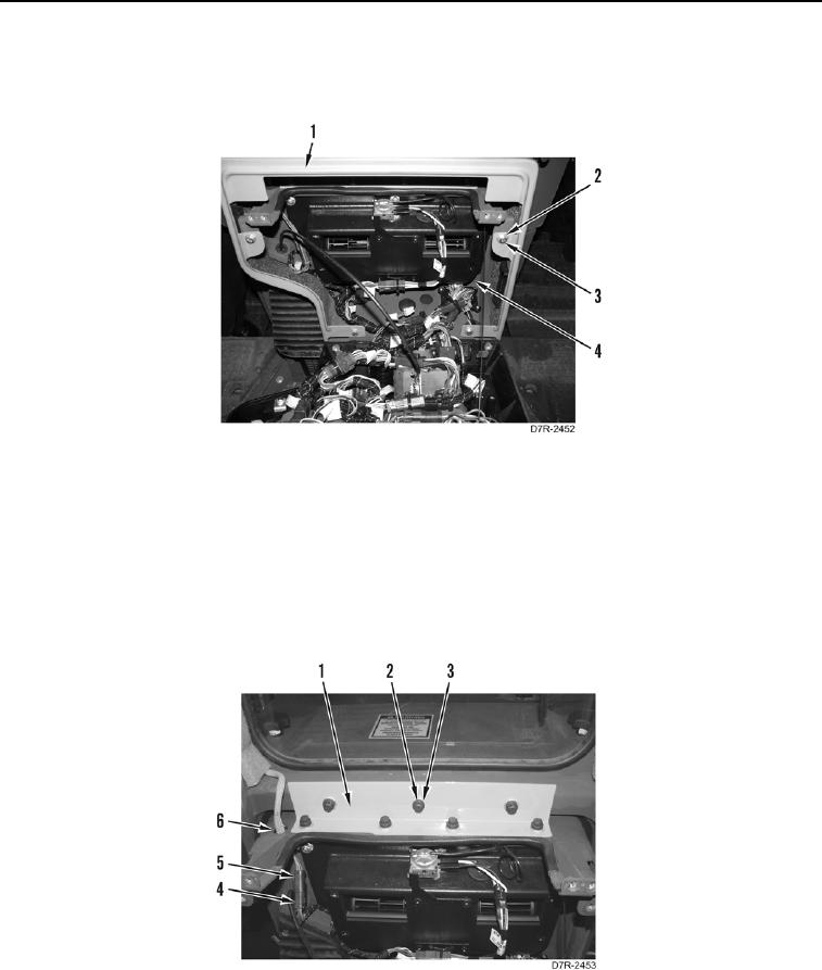
21. Disconnect wire harness connector (Figure 8, Item 5) from instrument panel connector (Figure 8, Item 4) and
position connector through hole in flange (Figure 8, Item 6).
22. Remove seven bolts (Figure 8, Item 3), washers (Figure 8, Item 2), and angle bracket (Figure 8, Item 1) from
instrument panel.
Figure 8. Harness Connector and Angle Bracket.
0245