
TM 5-2410-241-23-3
0245
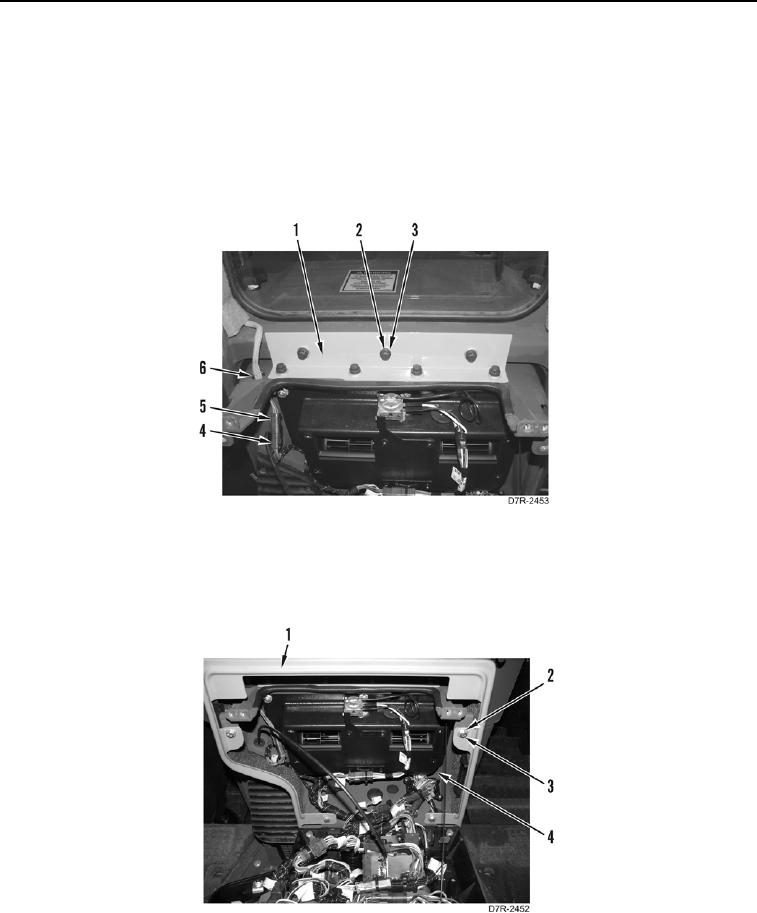
INSTALLATION CONTINUED
3. Install angle bracket (Figure 12, Item 1), seven washers (Figure 12, Item 2), and bolts (Figure 12, Item 3) on
instrument panel.
N OT E
Install all electrical harness connectors as noted during removal.
4. Position harness connector (Figure 12, Item 5) through hole in flange (Figure 12, Item 6) and connect wiring
harness connector (Figure 12, Item 5) to instrument panel connector (Figure 12, Item 4).
Figure 12. Harness Connector and Angle Bracket.
0245
5. Install panel (Figure 13, Item 1), four washers (Figure 13, Item 2), and bolts (Figure 13, Item 3) on instrument
panel (Figure 13, Item 4).
Figure 13. Surround.
0245