
TM 5-2410-241-23-3
0245
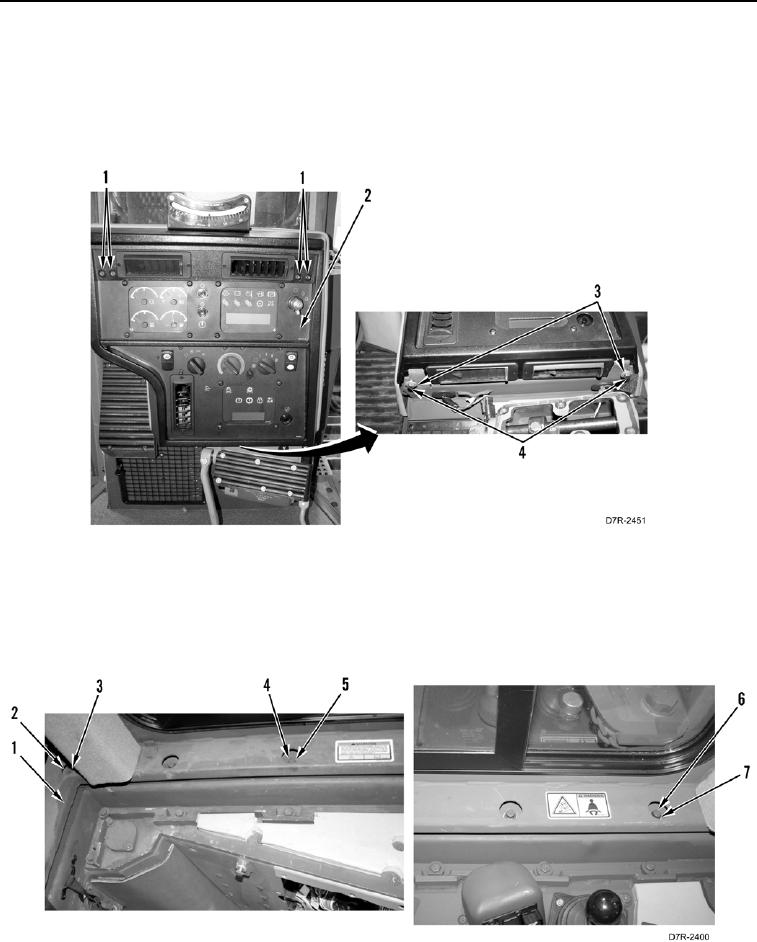
INSTALLATION CONTINUED
6. Raise instrument panel (Figure 14, Item 2) forward and hold up.
7. Install two washers (Figure 14, Item 3) and bolts (Figure 14, Item 4) on instrument panel (Figure 14, Item 2).
8. Install four bolts (Figure 14, Item 1) on instrument panel (Figure 14, Item 2).
9. Release instrument panel (Figure 14, Item 2).
Figure 14. Instrument Panel.
0245
10. Install six washers (Figure 15, Item 3) and bolts (Figure 15, Item 2) across back of cab (Figure 15, Item 1).
11. Install three washers (Figure 15, Item 7) and bolts (Figure 15, Item 6) on right side of cab (Figure 15, Item 1).
12. Install three washers (Figure 15, Item 5) and bolts (Figure 15, Item 4) on left side of cab (Figure 15, Item 1).
Figure 15. Cab Bolts.
0245