• Home
  • Download PDF
  • Order CD-ROM
  • Order in Print
Figure 5. Electrical Connector.
Figure 7. Brake Pedal, Foot Pad, and Sensor.

Field Maintenance Manual 3 D7R Dozer Type I With Winch and Type II With Ripper
Page Navigation
  674    675    676    677    678  679  680    681    682    683    684  
img
.
TM 5-2410-241-23-3
0258
REMOVAL CONTINUED
N OT E
Tag wiring harnesses and note routing to aid installation.
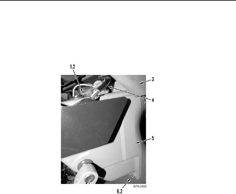
6. Remove two wiring harnesses (Figure 6, Item 4) from instrument panel (Figure 6, Item 3).
7. Remove two nuts (Figure 6, Item 1), washers (Figure 6, Item 2), bolts (Figure 6, Item 6), washers (Figure 6,
Item 2), and governor housing (Figure 6, Item 5) from machine.
Figure 6. Wiring Harnesses and Mounting.
0258
0258-5


Privacy Statement
Press Release
Contact

© Copyright Integrated Publishing, Inc.. All Rights Reserved.