• Home
  • Download PDF
  • Order CD-ROM
  • Order in Print
Figure 7. Brake Pedal, Foot Pad, and Sensor.
Figure 10. Decelerator Pedal.

Field Maintenance Manual 3 D7R Dozer Type I With Winch and Type II With Ripper
Page Navigation
  676    677    678    679    680  681  682    683    684    685    686  
img
.
TM 5-2410-241-23-3
0258
REMOVAL CONTINUED
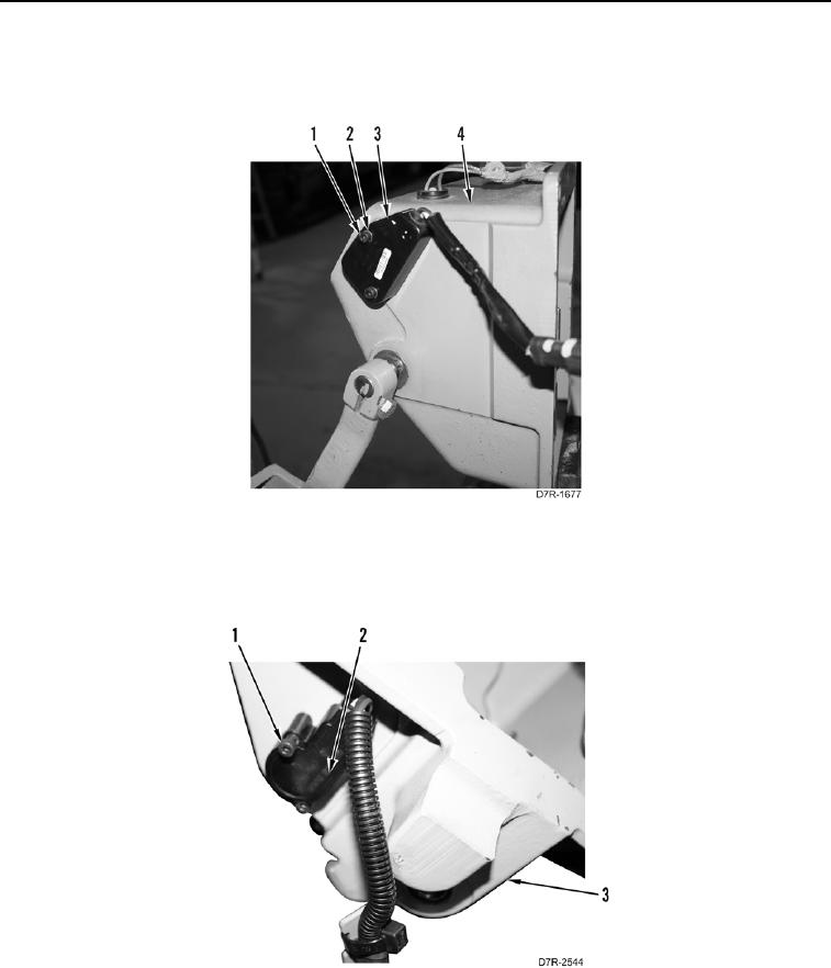
10. Remove two bolts (Figure 8, Item 1), washers (Figure 8, Item 2), and brake position sensor (Figure 8, Item 3)
from brake housing (Figure 8, Item 4).
Figure 8. Brake Pedal, Foot Pad, and Sensor.
0258
11. Remove two bolts (Figure 9, Item 1) and decelerator sensor (Figure 9, Item 2) from governor housing
(Figure 9, Item 3).
Figure 9. Sensor.
0258
0258-7


Privacy Statement
Press Release
Contact

© Copyright Integrated Publishing, Inc.. All Rights Reserved.