• Home
  • Download PDF
  • Order CD-ROM
  • Order in Print
Figure 6. Wiring Harnesses and Mounting.
Figure 8. Brake Pedal, Foot Pad, and Sensor.

Field Maintenance Manual 3 D7R Dozer Type I With Winch and Type II With Ripper
Page Navigation
  675    676    677    678    679  680  681    682    683    684    685  
img
.
TM 5-2410-241-23-3
0258
REMOVAL CONTINUED
N OT E
Mark shaft and brake pedal to aid installation.
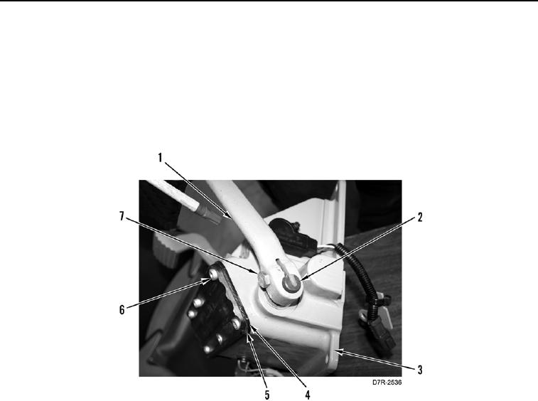
8. Loosen bolt (Figure 7, Item 7) and remove brake pedal (Figure 7, Item 1) from shaft (Figure 7, Item 2).
9. Remove six bolts (Figure 7, Item 6), foot pad (Figure 7, Item 5), and gasket (Figure 7, Item 4) from housing
(Figure 7, Item 3).
Figure 7. Brake Pedal, Foot Pad, and Sensor.
0258
0258-6


Privacy Statement
Press Release
Contact

© Copyright Integrated Publishing, Inc.. All Rights Reserved.