
TM 5-2410-241-23-3
0268
DISASSEMBLY CONTINUED
N OT E
Note orientation of knuckle on push arm and blade to aid installation.
The following steps will remove one pusharm. Repeat steps for other push arm.
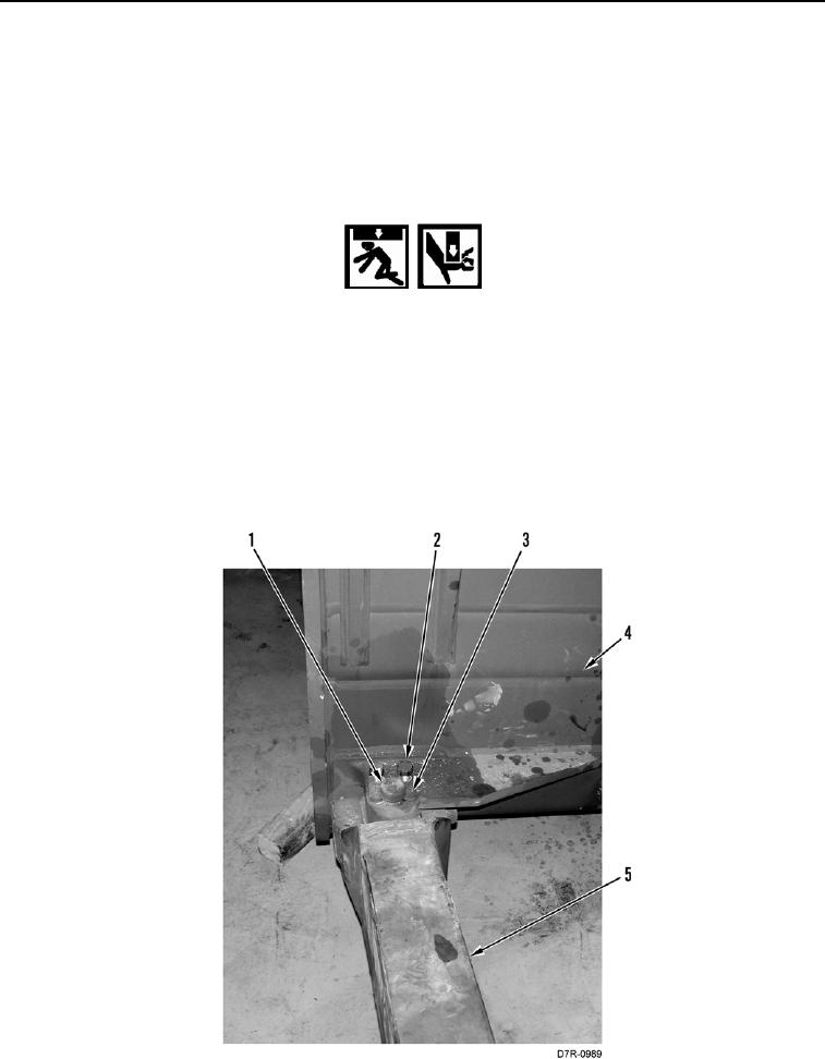
8. Remove two bolts (Figure 10, Item 2), lock (Figure 10, Item 3), pin (Figure 10, Item 1), from push arm
(Figure 10, Item 5) and blade assembly (Figure 10, Item 4).
WARN I N G
Use extreme caution when handling heavy parts. Provide adequate support and use
assistance during procedure. Ensure lifting device used is in good condition and of
suitable load capacity. Keep clear of heavy parts supported only by lifting device. Failure to
follow this warning may cause injury or death to personnel.
N OT E
Push arm weighs 880 lb (399 kg).
9. Attach lifting device to push arm (Figure 10, Item 5) and with assistance carefully separate push arm
(Figure 10, Item 5) from blade assembly (Figure 10, Item 4).
10. Remove lifting device.
Figure 10. Pin and Lock.
0268