
TM 5-2410-241-23-3
0297
CAB REMOVAL CONTINUED
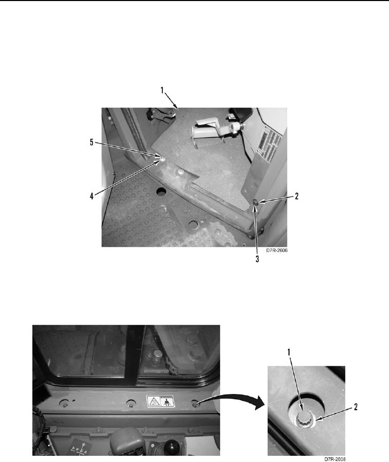
7. Remove floor mat (Figure 18, Item 1).
8. Remove four bolts (Figure 18, Item 5) and washers (Figure 18, Item 4).
9. Remove bolt (Figure 18, Item 3) and washer (Figure 18, Item 2).
10. Repeat steps 8 and 9 on opposite side of machine.
Figure 18. Cab Bolts at Door.
0297
11. Remove three bolts (Figure 19, Item 1) and washers (Figure 19, Item 2) from both sides below windows, and
six bolts and washers across back of cab below rear window.
Figure 19. Cab Bolts.
0297