• Home
  • Download PDF
  • Order CD-ROM
  • Order in Print
Figure 18. Cab Bolts at Door.
Figure 22. Wiring Harness Connector and Angle Bracket.

Field Maintenance Manual 3 D7R Dozer Type I With Winch and Type II With Ripper
Page Navigation
  1019    1020    1021    1022    1023  1024  1025    1026    1027    1028    1029  
img
.
TM 5-2410-241-23-3
0297
CAB REMOVAL CONTINUED
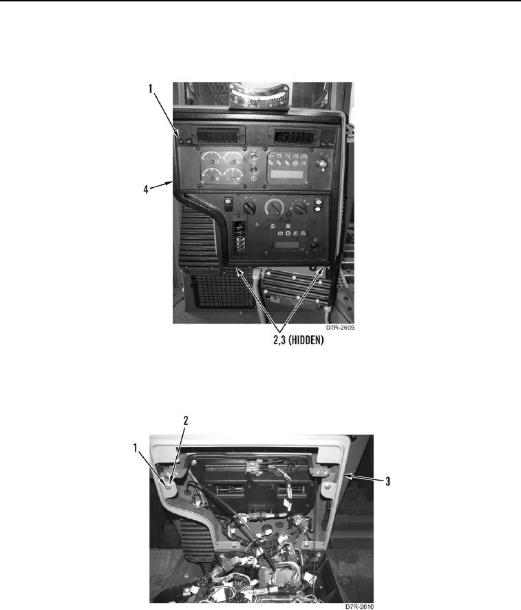
12. Remove four screws (Figure 20, Item 1) and two bolts (Figure 20, Item 2) from instrument panel (Figure 20,
Item 3). Tilt panel back and allow it to rest on support cable.
Figure 20. Instrument Panel.
0297
13. Remove four bolts (Figure 21, Item 1), washers (Figure 21, Item 2), and surround (Figure 21, Item 3).
Figure 21. Surround.
0297
0297-20


Privacy Statement
Press Release
Contact

© Copyright Integrated Publishing, Inc.. All Rights Reserved.