
TM 5-2410-241-23-3
0297
CAB INSTALLATION CONTINUED
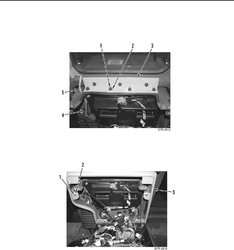
3. Install four washers (Figure 25, Item 2) and lower bolts (Figure 25, Item 1) on angle bracket (Figure 25, Item 3).
4. Route wiring harness connector through hole (Figure 25, Item 5) in flange and connect wiring harness
connector (Figure 25, Item 4).
Figure 25. Wiring Harness Connector and Angle Bracket.
0297
5. Install surround (Figure 26, Item 3), four washers (Figure 26, Item 2), and bolts (Figure 26, Item 1).
Figure 26. Surround.
0297