
TM 5-2410-240-10
0004
OPERATOR CONTROLS AND INDICATORS CONTINUED
Monitor System Gauges, Digital Display, and Ignition Switch
0004
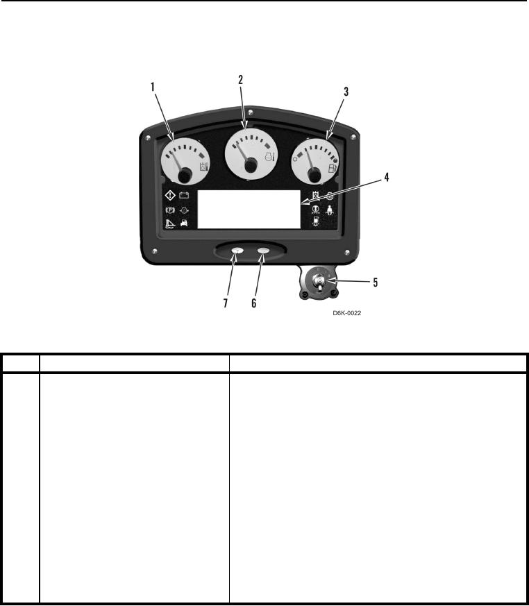
Figure 15. Monitoring System Gauges, Digital Display, and Ignition Switch.
0004
KEY
COMPONENT
DESCRIPTION
1
Hydraulic Temperature Gauge
Indicates temperature of oil in hydraulic sump.
2
Engine Coolant Temperature Gauge
Indicates temperature of engine coolant.
3
Fuel Level Gauge
Indicates approximate amount of fuel in fuel tank.
4
Digital Display Panel
Displays operational (service) hours, and selected forward
and reverse speeds.
5
Engine Start Switch
Turn switch clockwise to ON position to activate electrical
circuits in cab.
Turn switch clockwise to START position to start engine.
Turn switch counterclockwise to shut off engine and electrical
power.
If engine fails to start, switch must be returned to the OFF
position before attempting to start engine.
6
Scroll Button
Scrolls through operator mode menus.
7
Mode Button
Scrolls through operator modes