TM 5-2410-240-23-1
0011
IMPLEMENT HYDRAULIC SYSTEM CONTINUED
Winch (D6K with Winch)
00011
The winch has four functions: REEL IN, REEL OUT, FREE SPOOL, and BRAKE OFF.
The equipment ECM controls the free spool solenoid, reel-in solenoid, reel-out solenoid, and drive-away solenoid
outputs based on requests from the machine ECM. The machine ECM controls the winch brake solenoid output.
The equipment ECM communicates with the machine ECM by means of the Controller Area Network (CAN) bus.
The pump for the winch is very similar to the pumps found in the hydrostatic system except for the following:
A Pressure Override Relief (POR)valve limits maximum system pressure in the winch system whereas the
hydrostatic system uses a pressure transducer.
Proportional solenoidscontrol the F-N-R valve.
Pilot oil from the implement pilot shutoff valve releases the winch brake and the winch's clutch spool. Pilot oil also
activates the drive-away solenoid valve.
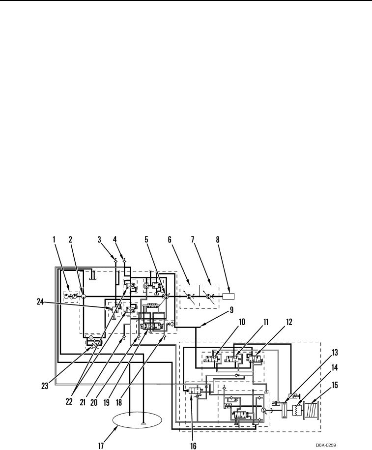
The fan pump (Figure 15, Item 1) is a gear pump. The fan pump provides oil to the cooling fan and to the left side
hydrostatic pump (Figure 15, Item 7). Oil from the fan pump flows through the passage (Figure 15, Item 9) to the
winch control valves (Figure 15, Items 10 and 12). Excess oil returns to the tank (Figure 15, Item 17) through the
open centered solenoid valve (Figure 15, Item 19) for the winch pump (Figure 15, Item 5). Oil from the fan pump
flows to the brake valve. If the brake valve is open, oil pressure will overcome the force of the springs and release
the brake (Figure 15, Item 13). Oil from the fan pump flows to the free spool valve. If free spool valve is open, the
oil pressure will overcome the force of the springs and release free spool clutch (Figure 15, Item 14). The oil from
the fan pump flows to drive-away valve (Figure 15, Item 12). If drive-away valve is open, oil pressure will activate
the drive-away function.
Figure 15. Winch Operation.
0011

