
TM 5-2410-240-23-1
0011
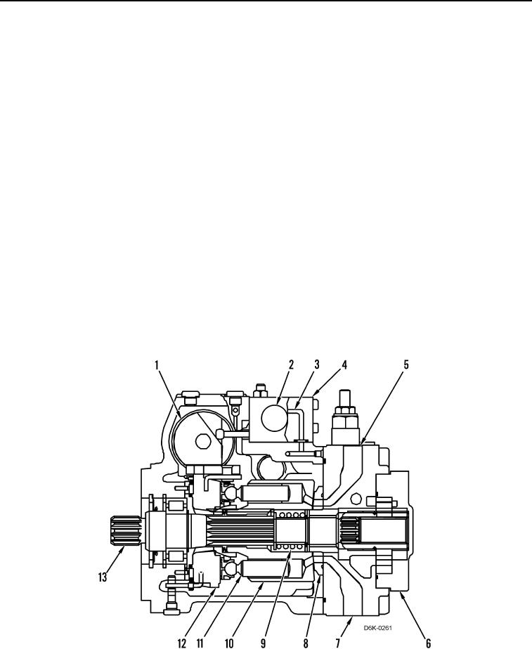
IMPLEMENT HYDRAULIC SYSTEM CONTINUED
2. Winch Pump - Operation
When the engine is running, the shaft (Figure 17, Item 13) and barrel (Figure 17, Item 10) rotate. The port plate
(Figure 17, Item 8) and swashplate (Figure 17, Item 12) are stationary within the pump housing. The spring
(Figure 17, Item 9) maintains a force against the barrel and the port plate. There are nine pistons (Figure 17,
Item 11) in the barrel. When the barrel is rotating, each piston follows the angle of the swashplate. If the angle of
swashplate is zero, the pistons do not move in and out of the barrel and there is no oil flow. Charge oil from the
charge pump (Figure 17, Item 6) maintains oil pressure in the pump in order to perform the following tasks:
Keep barrel (Figure 17, Item 10) full of oil.
Provide makeup oil for internal leakage.
Lubricate pump components.
Provide oil to solenoid valve (Figure 17, Item 4) in orde to shift actuator piston (Figure 17, Item 1) and change
r
the angle of swashplate (Figure 17, Item 12).
The actuator piston (Figure 17, Item 1) determines the position of the swashplate (Figure 17, Item 12). The
machine Electronic Control Module (ECM) interprets commands from the winch control lever and sends
commands to the proportional solenoid valve (Figure 17, Item 2). The proportional solenoid valve directs oil
through the passage (Figure 17, Item 3) to the corresponding end of the actuator piston. As the actuator piston
begins to move, the angle of the swashplate begins to increase. As the pistons (Figure 17, Item 11) follow the
swashplate, the pistons begin to move in and out of the barrel (Figure 17, Item 10). As the piston moves out of the
barrel, oil is drawn from the reel-out port (Figure 17, Item 5) of the winch through the port plate (Figure 17, Item 8).
As the piston follows the swashplate and the pistons move into the barrel, oil is pushed through the port plate into
the reel-in port (Figure 17, Item 7) of the loop. As the angle of the swashplate increases, the output flow of the
pump also increases.
Figure 17. Winch Pump Operation.
0011