
TM 5-2410-240-23-1
0011
IMPLEMENT HYDRAULIC SYSTEM CONTINUED
Proportional Priority Pressure Compensation (PPPC) System
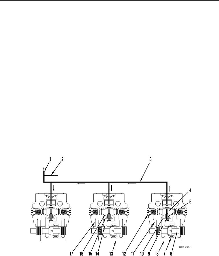
00011
The Proportional Priority Pressure Compensated System (PPPC) directs pump discharge oil to each individual
implement circuit in proportion to the movement of the implement control lever. The implement circuit with the
highest working pressure provides the true load signal pressure during multiple functions.
Pump oil flow is directed into the chamber (Figure 14, Item 7). When the control valve (Figure 14, Item 8) is
activated, pump flow is directed into the feeder passage (Figure 14, Item 9). Oil in the feeder passage pushes the
piston for the flow compensator (Figure 14, Item 4) upward. The pump oil flows through openings in the bottom of
the piston for flow compensator (Figure 14, Item 10) to the bridge passage (Figure 14, Item 11). In order for the oil
to get from the feeder passage to the bridge passage, the pressure must be high enough to overcome the spring in
the check valve (Figure 14, Item 12). From the bridge passage, pump flow is directed around the control valve
spool (Figure 14, Item 6) to the work port.
When the piston for the flow compensator (Figure 14, Item 4) is pushed upward, oil in the feeder passage
(Figure 14, Item 9) is also directed through the cross-drilled passage (Figure 14, Item 5) to the signal pressure
passage (Figure 14, Item 3). The flow of oil through the cross-drilled passage supplements the oil from the
hydrostatic charge pump (Figure 14, Item 2). The combined flow of oil is directed to the top of the pistons for the
flow compensators of the other control valves and to the pump control valve (Figure 14, Item 1). The pump control
valve causes the pump to upstroke in order to increase the flow.
If a second control valve (Figure 14, Item 13) is partially opened, the same basic steps occur. Pump flow is directed
into the feeder passage (Figure 14, Item 14). The oil in the feeder passage pushes the piston for the flow
compensator (Figure 14, Item 16) upward. Pump oil flows through openings in the bottom of the flow compensator
piston (Figure 14, Item 15) to the bridge passage (Figure 14, Item 17) in proportion to the movement of the
implement control lever. The piston for the flow compensator will not rise fully because of signal pressure from the
control valve (Figure 14, Item 8). The signal with the highest work port pressure regulates the flow through all
activated control valves.
Figure 14. Proportional Priority Pressure Compensation (PPPC) System.
0011