
TM 5-2410-240-23-1
0011
IMPLEMENT HYDRAULIC SYSTEM CONTINUED
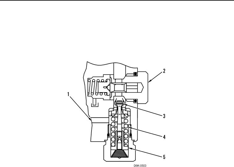
8. Relief Valve - Operation
Oil flows from the drive loop to the crossover relief valve through the passage (Figure 21, Item 1). Oil pressure acts
against the surface of the poppet (Figure 21, Item 3). Since the poppet screws into the spring retainer (Figure 21,
Item 5), the retainer attempts to compress the spring (Figure 21, Item 4). When oil pressure overcomes the force of
the spring, the poppet moves upward. Oil flows from the passage past the poppet and through charge relief valve
(Figure 21, Item 2) to the case drain.
Figure 21. Relief Valve.
0011