
TM 5-2410-240-23-1
0011
IMPLEMENT HYDRAULIC SYSTEM CONTINUED
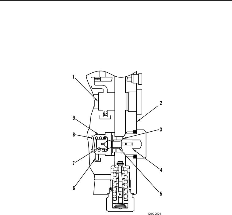
9. Charge Pressure Relief Valve Operation
Charge oil from the hydraulic oil filter flows through the passage (Figure 22, Item 1) to the passage (Figure 22,
Item 2) and then through the port (Figure 22, Item 3) to the poppet (Figure 22, Item 4). When the pressure against
the seating surface (Figure 22, Item 5) overcomes the force of the spring (Figure 22, Item 8), the poppet moves to
the left and pushes the spring retainer (Figure 22, Item 7) against the force of the spring. Oil flows past the poppet
into the spring chamber (Figure 22, Item 9) and then through the passage (Figure 22, Item 6) to the piston pump's
case drain. The poppet oscillates as the flow of charge oil fluctuates in order to maintain a constant pressure for the
charge oil.
Figure 22. Charge Pressure Relief Valve.
0011