
TM 5-2410-240-23-1
0024
ENGINE VALVE LASH INSPECT/ ADJUST
0024
Valve Lash Check
0024
WARN I N G
Accidental engine starting can cause injury or death to personnel. To prevent accidental
engine starting, turn ignition switch to OFF position and place a Do Not Operate tag at
ignition switch location.
N OT E
Check valve lash while engine is stopped.
When valve mechanism cover is removed or installed, electrical harness must be
checked. Do not pinch injector harness when valve mechanism cover is installed. Do not
allow harness to be in contact with valve mechanism cover. Replace harness if damaged.
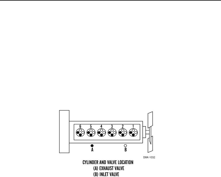
Cylinder and Valve Location includes exhaust valves (Figure 1, Item A) and inlet valves
(Figure 1, Item B).
Figure 1. Cylinder and Valve Location.
0024
1. Remove valve cover (WP 0104).