
TM 5-2410-240-23-1
0024
ENGINE VALVE LASH INSPECT/ ADJUST CONTINUED
N OT E
Firing order is 1-5-3-6-2-4. No. 1 cylinder is at front of engine.
Refer to Table 1 valve lash sequence for proper order.
Valve is open when rocker armis in the full down position.
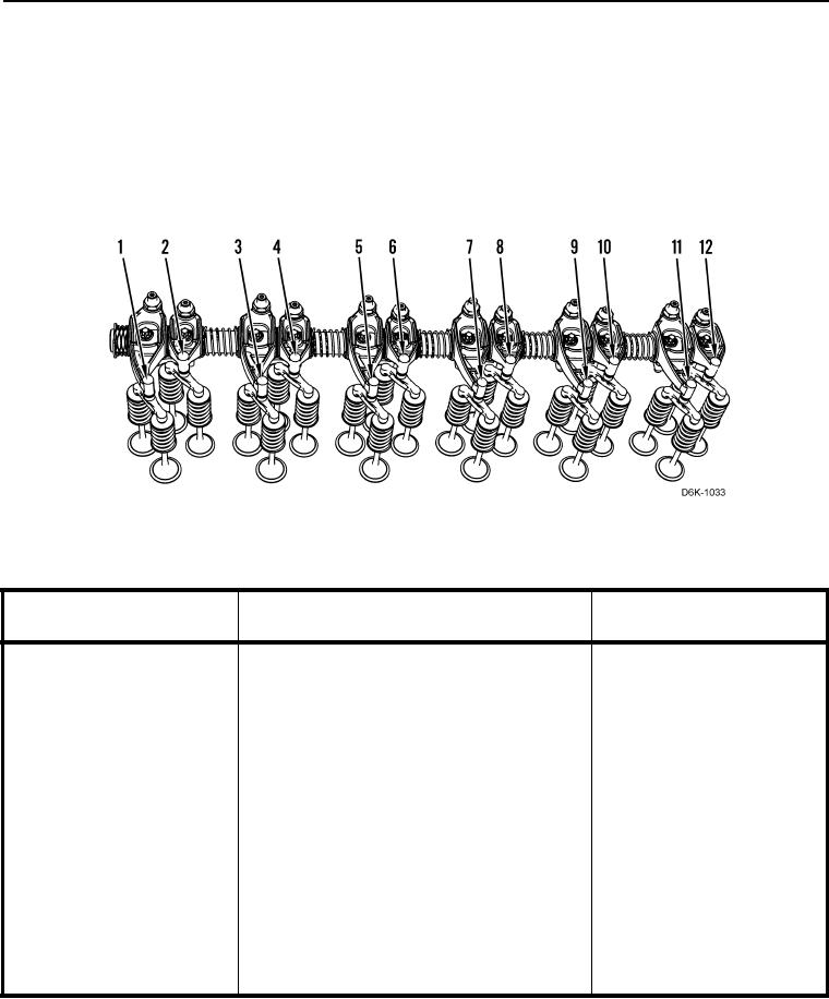
2. Rotate crankshaft clockwise until inlet valves (Figure 2) are fully open for specified cylinder (Table 1).
Figure 2. Cylinder and Valve Location.
0024
Table 1. Valve Lash Sequence (Refer to Figure for Numbers).
Rotate Crankshaft Until
Inlet Valves
Exhaust Valves
Inlet Valves are Fully Open
(Cylinder Numbers)
(Cylinder Numbers)
11
9
10
(6)
(5)
(5)
3
5
6
(2)
(3)
(3)
7
11
12
(4)
(6)
(6)
1
3
4
(1)
(2)
(2)
9
7
8
(5)
(4)
(4)
1
2
(5)
(1)
(1)
3