
TM 5-2410-240-23-1
0031
TRANSMISSION STALL TEST CONTINUED
00031
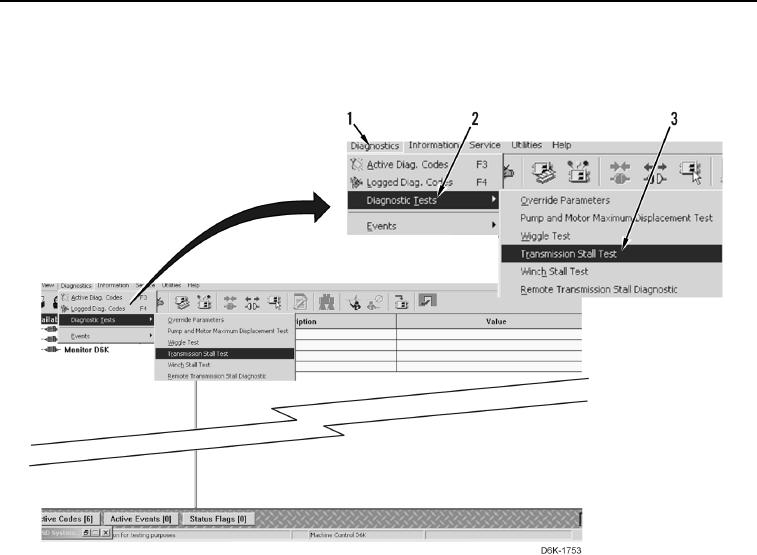
9. Select Diagnostics (Figure 3, Item 1), Diagnostic Tests (Figure 3, Item 2), and Transmission Stall Test (Figure
3, Item 3).
Figure 3. Transmission Stall Test.
0031
Test
00031
N OT E
Procedure requires testing at four pressure taps simultaneously. If four gauges and test
hoses are not available, install pressure gauges on pressure tap on test panel and
corresponding pressure tap on pump, then perform Transmission Stall Test. Switch
pressure gauges for remaining pressure taps listed and perform Transmission Stall Test.
1. Start and run engine at low idle, set parking brake (TM 5-2410-240-10), and verify parking brake indicator is
on.
2. Select ground speed of 1.0 on compact instrument cluster (CIC) (TM 5-2410-240-10).
3. Increase engine speed to high idle and record engine speed.
4. Position steering and transmission control to FORWARD position (TM 5-2410-240-10). Tracks should not
move.
5. Monitor and record pressure readings at left side hydrostatic pump pressure tap and right side hydrostatic
pump pressure tap on test panel.
a. Left hydrostatic pump pressure should be 6,563 290 psi (45,250 2,000 kPa).
b. Right hydrostatic pump pressure should be 6,476 290 psi (44,650 2,000 kPa).