
TM 5-2410-240-23-1
0031
CROSSOVER RELIEF VALVE ADJUST CONTINUED
N OT E
Procedure requires testing at four pressure taps simultaneously. If four gauges and test
hoses are not available, install pressure gauges on pressure tap on test panel and
corresponding pressure tap on pump, then perform test. Switch pressure gauges for
remaining pressure taps listed and perform test.
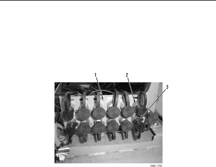
10. Stop engine and relieve hydraulic system pressure (WP 0162). Install pressure gauge at left side hydrostatic
pump pressure tap (Figure 18, Item 2) and right side hydrostatic pump pressure tap (Figure 18, Item 3) on test
panel (Figure 18, Item 1). Refer to WP 0291 for pressure gauge and hose setup.
Figure 18. Test Panel.
0031