
TM 5-2410-240-23-1
0031
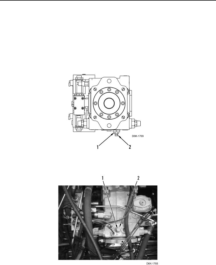
CHARGE RELIEF VALVE - ADJUST CONTINUED
N OT E
One full turn of adjustment screw is equal to approximately 55 psi (380 kPa).
2. Loosen locknut (Figure 15, Item 1) and turn adjustment screw (Figure 15, Item 2). Use the following procedure
for adjustment:
a. Turn adjustment screw counterclockwise to decrease pressure. Turn adjustment screw 1/4 turn beyond
estimated adjustment position and then back to estimated adjustment position.
b. Turn adjustment screw clockwise to increase pressure.
3. Maintain position of adjustment screw (Figure 15, Item 2) as locknut (Figure 15, Item 1) is tightened.
Figure 15. Locknut and Adjustment Screw.
0031
4. Install new cap (Figure 16, Item 1) on charge relief valve (Figure 16, Item 2).
Figure 16. Charge Relief Valve.
0031
END OF TASK