
TM 5-2410-240-23-2
0041
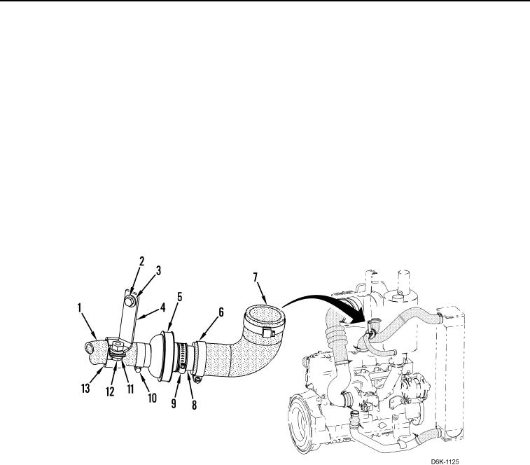
CHECK VALVE REMOVAL
00041
N OT E
Tag and mark hoses to aid installation.
Cap hose ends and plug open ports.
1. Remove bolt (Figure 4, Item 12), washer (Figure 4, Item 11), and two brackets (Figure 4, Items 4 and 13) from
hose (Figure 4, Item 1).
2. Remove bolt (Figure 4, Item 2), washer (Figure 4, Item 3), and bracket (Figure 4, Item 4) from machine.
3. Loosen three clamps (Figure 4, Item 10) and remove hose (Figure 4, Item 1) from machine.
4. Remove three clamps (Figure 4, Item 10) from hose (Figure 4, Item 1).
5. Loosen clamp (Figure 4, Item 9) and remove check valve (Figure 4, Item 5) from tube (Figure 4, Item 8).
6. Remove clamp (Figure 4, Item 9) from check valve (Figure 4, Item 5).
7. Loosen two clamps (Figure 4, Item 6) and remove hose (Figure 4, Item 7) from machine.
8. Remove two clamps (Figure 4, Item 6) and tube (Figure 4, Item 8) from hose (Figure 4, Item 7).
Figure 4. Check Valve.
0041
END OF TASK
CLEANING AND INSPECTION
00041
Clean and inspect all parts IAW Mechanical General Maintenance Instructions (WP 0282).
END OF TASK